- 您现在的位置:买卖IC网 > Sheet目录1994 > DS1672S-3/T&R (Maxim Integrated Products)IC TIMEKEEPER 3V 32-BIT 8-SOIC
DS1672
10 of 15
Trickle Charger
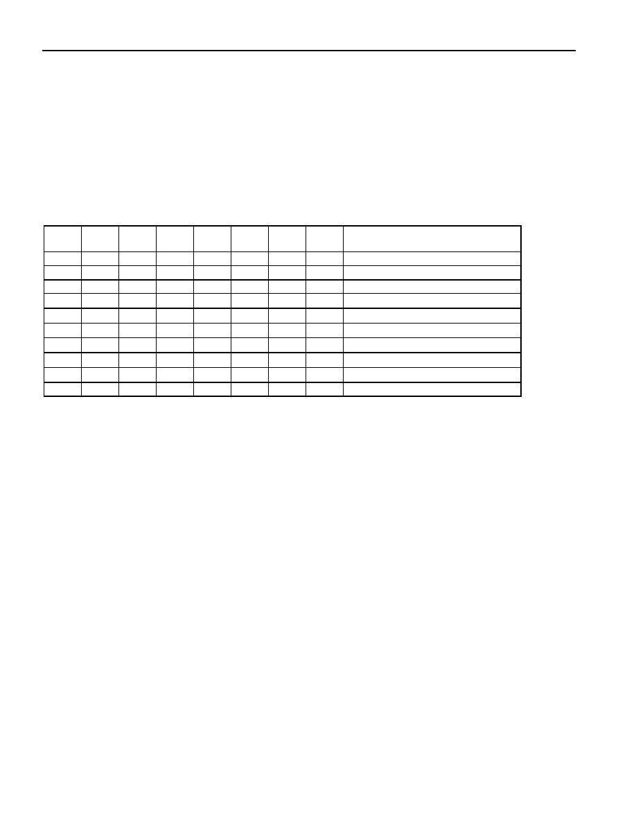
The trickle charger is controlled by the trickle charge register. The simplified schematic of Figure 5
shows the basic components of the trickle charger. The trickle charge select (TCS) bit (bits 4–7) controls
the selection of the trickle charger. In order to prevent accidental enabling, only a pattern on 1010 will
enable the trickle charger. All other patterns will disable the trickle charger. The DS1672 powers up with
the trickle charger disabled. The diode select (DS) bits (bits 2, 3) select whether or not a diode is
connected between VCC and VBACKUP. If DS is 01, no diode is selected or if DS is 10, a diode is selected.
The RS bits (bits 0, 1) select whether a resistor is connected between VCC and VBACKUP and what the value
of the resistor is. The resistor selected by the resistor select (RS) bits and the diode selected by the diode
select (DS) bits are as follows:
TCS
DS
RS
FUNCTION
X
0
X
Disabled
X
1
X
Disabled
X
0
Disabled
1
0
1
0
1
0
1
No diode, 250
resistor
1
0
1
0
1
0
1
One diode, 250
resistor
1
0
1
0
1
0
No diode, 2k
resistor
1
0
1
0
1
0
1
0
One diode, 2k
resistor
1
0
1
0
1
No diode, 4k
resistor
1
0
1
0
1
0
1
One diode, 4k
resistor
0
Initial default value--disabled
Warning: The resistor value of 250
must not be selected whenever V
CC is greater
than 3.63V.
Diode and resistor selection is determined by the user according to the maximum current desired for
battery or super cap charging. The maximum charging current can be calculated as illustrated in the
following example. Assume that a system power supply of 3V is applied to VCC and a super cap is
connected to VBACKUP. Also assume that the trickle charger has been enabled with a diode and resistor R2
between VCC and VBACKUP. The maximum current IMAX would, therefore, be calculated as follows:
IMAX = (5.0V - diode drop) / R1 ≈ (5.0V - 0.6V) / 2k ≈ 2.2mA
As the super cap changes, the voltage drop between VCC and VBACKUP will decrease and, therefore, the
charge current will decrease.
发布紧急采购,3分钟左右您将得到回复。
相关PDF资料
DS1673S-3
IC CTRLR SYSTEM PORT 3V 20-SOIC
DS1677E
IC CTRLR SYSTEM PORT 20-TSSOP
DS1678S/T&R
IC RECORDER REALTIME EVENT 8SOIC
DS1682S
IC TIMEKEEPER ALARM ELAPSE 8SOIC
DS1683S+T&R
IC REAL TIME EVENT REC 8SOIC
DS1685EN-5/T&R
IC RTC 5V 64BIT Y2K IND 24TSSOP
DS1688S+
IC RTC W/NV RAM CTRL 28-SOIC
DS1689SN+T&R
IC RTC SER NV RAM CTRL IN 28SOIC
相关代理商/技术参数
DS1672S-3/TR
制造商:MAXIM 制造商全称:Maxim Integrated Products 功能描述:I2C 32-Bit Binary Counter RTC
DS1672S-3+
功能描述:实时时钟 I2C 32-Bit Binary Counter RTC RoHS:否 制造商:Microchip Technology 功能:Clock, Calendar. Alarm RTC 总线接口:I2C 日期格式:DW:DM:M:Y 时间格式:HH:MM:SS RTC 存储容量:64 B 电源电压-最大:5.5 V 电源电压-最小:1.8 V 最大工作温度:+ 85 C 最小工作温度: 安装风格:Through Hole 封装 / 箱体:PDIP-8 封装:Tube
DS1672S-3+T&R
制造商:Maxim Integrated Products 功能描述:REAL TIME CLOCK SERL 8SOIC - Tape and Reel 制造商:Maxim Integrated Products 功能描述:IC TIMEKEEPER 3V 32-BIT 8-SOIC 制造商:Maxim Integrated Products 功能描述:Real Time Clock I2C 32-Bit Binary Counter RTC
DS1672S-3+T&R
功能描述:实时时钟 I2C 32-Bit Binary Counter RTC RoHS:否 制造商:Microchip Technology 功能:Clock, Calendar. Alarm RTC 总线接口:I2C 日期格式:DW:DM:M:Y 时间格式:HH:MM:SS RTC 存储容量:64 B 电源电压-最大:5.5 V 电源电压-最小:1.8 V 最大工作温度:+ 85 C 最小工作温度: 安装风格:Through Hole 封装 / 箱体:PDIP-8 封装:Tube
DS1672S-3+TR
制造商:MAXIM 制造商全称:Maxim Integrated Products 功能描述:I2C 32-Bit Binary Counter RTC
DS1672S-33
功能描述:实时时钟 I2C 32-Bit Binary Counter RTC RoHS:否 制造商:Microchip Technology 功能:Clock, Calendar. Alarm RTC 总线接口:I2C 日期格式:DW:DM:M:Y 时间格式:HH:MM:SS RTC 存储容量:64 B 电源电压-最大:5.5 V 电源电压-最小:1.8 V 最大工作温度:+ 85 C 最小工作温度: 安装风格:Through Hole 封装 / 箱体:PDIP-8 封装:Tube
DS1672S-33/T&R
制造商:Maxim Integrated Products 功能描述:REAL TIME CLOCK SERL 8SOIC - Tape and Reel 制造商:Maxim Integrated Products 功能描述:IC TIMEKEEPER 3.3V 32-BIT 8-SOIC 制造商:Maxim Integrated Products 功能描述:Real Time Clock I2C 32-Bit Binary Counter RTC
DS1672S-33/T&R
功能描述:实时时钟 I2C 32-Bit Binary Counter RTC RoHS:否 制造商:Microchip Technology 功能:Clock, Calendar. Alarm RTC 总线接口:I2C 日期格式:DW:DM:M:Y 时间格式:HH:MM:SS RTC 存储容量:64 B 电源电压-最大:5.5 V 电源电压-最小:1.8 V 最大工作温度:+ 85 C 最小工作温度: 安装风格:Through Hole 封装 / 箱体:PDIP-8 封装:Tube